Saturday, 29 November 2014

Xmas tree lights with the Raspberry Pi

Now I've seen many where people have cut the power line to the lights and run them through relays that you can turn on and off. Now that was my original idea for this year but after some researching I came across this brilliant article on the adafruit site by Tony Dicola https://learn.adafruit.com/neopixels-on-raspberry-pi/

My first stumble block was I needed to install setuptools so I could install easy install, but once I had this in place it was only a matter of minutes before I had the lights working.

So what do you need? Well neopixels rgb with a good power supply (5v 5a) is what I'm using. Power lead to power the power converter/supply some wire and a sn74ahct125n chip.


Now I needed something a bit more secure so wires didn't accidentally drop out so with Tony's great instructions I turned the breadboard diagram into a PCB board and got my friends at Ragworm to make me up a board (which are costly for the odd one boards). Ok I could have gone abroad but wanted to ensure I had it in time for Xmas.

After soldering up the bits and plugging into the gpio, I setup the neopixels and ran the strand test.py demo. It needed a tweak to tell it I was running 160 neopixels (which might be less when it's finally on the tree) but found it worked.

I have added some videos of it onto my YouTube page to show it working.


Next on my list is to turn the brightness down and make them glow Christmassy colours.

Friday, 7 November 2014

The MyPiFi 10 LED Bar on Kickstarter

I decided after using a great book for the arduino by Mark Geddes called the arduino project handbook that I needed something a bit more permanent for the LEDs and for future things, so I came up with this LED light bar.


It comes with two rows on the bottom, a male row and an identical row but with female headers, you don't even need to even put both rows in, but how many times have you got stuck on a project as you run out of one type of jumper cable that you need but have plenty of the other that you don't need?

So I decided to Kickstart my idea £6 a board and so far I have managed to decrease the size to 51x31mm and designed in a way that you can line all the boards next to each other and make one massive LED light bar.

Currently the 21 day Kickstarter is down to nearly 14 days left and 25% funded. There are plenty stretch goals listed should we go through the funded barrier early, so to enjoy some of these great stretch goals please get pledging early and lastly this should be with you in time to solder for Christmas Day.


Sunday, 26 October 2014

Croydon raspberry jam

Today was Croydons first raspberry jam, I had arrived early before spending ages searching for the venue which incidentally  was on the floor I arrived on which had this great lighting effect that changed colour.


I was greeted by Jarle and the people behind the lives not knives community project who were very accommodating and so pleased we were able to come.

I was able to show off some of my boards and had donated a ton of version one rectangular boards for the soldering workshop.


PiTop were there with their brilliant 3d printed computers that are currently available on indigogo a crowd funding platform.  What I liked about these was how they glowed on the back when in use, lighting up the case.


There was plenty to do with mine craft coding to which is always popular and average man vs pi was there with his huge display of pi bits and his protocam which was great to see.  There is also a time lapse video he made along with his ever so bright selfie camera which I look forward to seeing on his blog soon.

Whaleygeek brought along his light project that you could change the lighting effect on as well as his brilliant rfid project that played the sound of the picture on the rfid card showing one of many possibilities for rfid and a project I will want to try soon.

Derek from the Southend jams brought along sonic pi and gave some brilliant demonstrations of what can be done with this which lead to a local youth to make some modern beats with it.


Along with the talks in this spacious but very relaxing venue, everyone was looked  after and certainly was worth the long drive in, just didn't like the fact I had a 100 mile journey ahead of me to get back home.


Friday, 24 October 2014

Getting started with the MyPiFi LCD Board kit


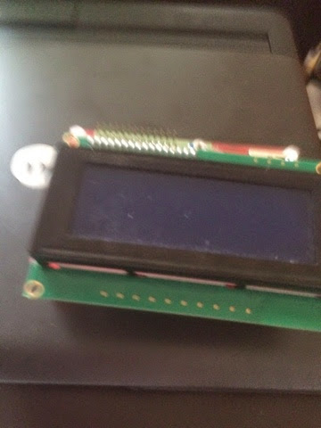
Opening up the packet you will be greeted with these parts, the board, extended gpio header, 16 pin socket for the lcd to plug into and potentiometer for adjusting the screen.

firstly we want to start with the gpio, with a bit of blue tack or putty secure the board in place the will ensure you get a perfect right angle connection and not become skew whiff.


Next is the potentiometer, keep the flat side to the left as per picture so the two pins on the flat side go in the two holes and the single pin under the curved area on the right will go in the hole on the right  as per picture.


Now it's time to add the 16 way header, this is so you can swap and change between lcd boards, if you really don't want to swap you could solder the LCD board straight to it, but for this tutorial I will treat the board as I originally designed it for. However if you go straight to the bottom I have added how to do this and make it more permanent.


Again the putty is a great way to hold it all in place whilst soldering the pins.

Now, providing you have soldered the pins to the LCD board and plugged it in we are ready to move on to the software side of things.


Following Jason's great blog post  http://www.boeeerb.co.uk/pi-lcd/ don't forget to reboot at the end with:

Sudo shutdown -r now

When you restart you should be greeted with something like this.


At the bottom of the blog on boeeerb there are a couple of demo scripts, here is a picture to show it working.


The whole thing from start to finish should take you around 1-2 hours depending on how much updates your device needs, solder skills and typing speed.

More can be found on eBay and various raspberry pi online shops.

Making the board support more permanent:

If you decide on a more permanent solution, don't solder the black 16 pin to the board, solder the male 16 pin header so the shortest end goes into the MyPiFi board then place the LCD over the longer pins and solder, you need to do it this way round or the pins could touch the pi.  You could once soldered cut the pins down to make them flush.


Thank you to averagemanvspi who has listed the pins as: LCD_RS = 7, LCD_E  = 8, LCD_D4 = 25, LCD_D5 = 24, LCD_D6 = 23, LCD_D7 = 18 (BCM numbering)


Also thank you to @boeeerb for his write up for lcdproc and the fritzing picture.

PenguinTutor has written about his experience with his here. http://www.penguintutor.com/news/raspberrypi/pibow-lcd

LCD Schemetics:

 
Here are some of the tweets I've recieved from users:


Penguintutor has also done a brilliant guide to get started here: http://www.penguintutor.com/programming/raspi-lcd

Wednesday, 8 October 2014

Piface Internet radio

I decided my old model A pi would make a great Internet radio.  Needing something quick I dug out my pifacecad board a wifi dongle and after following this guide http://www.piface.org.uk/products/piface_control_and_display/ soon had it up and running.  Whilst the touchscreen one I made last week could control the volume, this one you have to rely on the volume buttons on the speaker but certainly uses less amps than the touchscreen version.


My next task is to get the ir remote working with it and look into being able to play other streams apart from the .pls which it seems to be the only version I can get to work on it at the moment.

It works using player so I might have to look at running mpd and mpc on it and hopefully this will give more info on the screen.

Friday, 3 October 2014

Touchscreen Internet radio

Came across on Twitter a while back an Internet radio with touchscreen.

Having all the bits it didn't take long to set up and a great guide has now appeared on Adafruit https://learn.adafruit.com/raspberry-pi-radio-player-with-touchscreen/overview

I have since edited rc.local and added

cd /home/pi/Radio/
Sudo Python radioplayer.py 


With this in there the radio loads up automatically and if you hold the button down second from left for three seconds this will shut it down.


I also have a nice sonic pi speaker and a usb wifi dongle plugged in and using a 240v - 5v 2a plug similar to th iPhone charger socket plus usb lead to run this.

Thursday, 25 September 2014

Three ideas for your MyPiFi LCD Board

Three ideas I have made with LCDs and a raspberry pi, just to get you going with your MyPiFi LCD Support Board kit for the pi on kickstarter https://www.kickstarter.com/projects/1059145052/mypifi-lcd-board-support


1.  The Cacheberry pi geocaching device.  You can also use this as a petrol station locator, speed camera locator or even just have it to only show speed/time/date http://smstextblog.blogspot.co.uk/2014/01/cacheberry-pi-in-detail.html

2.  Weather forecaster/news/football scores.  This one involves using RSS feeds to display the latest news/forecast/result or to whatever you want to show.  Don't dorget you could program it with a Twitter api to show your tweets or follow a hashtag http://smstextblog.blogspot.co.uk/2013/12/raspberry-pi-lcd-weather-station.html

3.  Radio display, whilst this project uses an adafruit lcd plate, you could use the Mypifi lcd board add a couple of buttons and speaker and use the mypifi kit to play radio and view station info.  http://smstextblog.blogspot.co.uk/2013/07/wipi-radio.html

If you have any great lcd projects feel free to post them all below, don't forget to take a look at our kickstarter https://www.kickstarter.com/projects/1059145052/mypifi-lcd-board-support

Sunday, 21 September 2014

Piduino

Recently I received one of these beauties. It's like a raspberry pi but runs arduino boards and arduino IDE on it.


So firstly was to go to the pcduino site and download the zip file, unzip it and copy to a sd card (an .img and .sh file) don't use win image or anything like that, straight forward drop and go.

Next plug the card in and turn on the device which welcomes you with the pcduino page before it copies the contents to the onboard chip and whalla the board now has Ubuntu on it with all the essential programs and if anything is a great cheap computer just for that but there's more.

The board also comes with extra connections like Ethernet, wifi, usb and IR on this 1ghz board.

So far I've been very impressed with it and like the all in one feel for using a small computer and arduino together and  for £55 quid certainly worth it.  If after a while you have enough then I'm sure it could be a great XBMC device.


Here are the specs.

ItemsDetails
CPUAllWinner A20 SoC, 1GHz ARM Cortex A7 Dual Core
GPUOpenGL ES2.0, OpenVG 1.1, Mali 400 Dual Core
DRAM1GB
Onboard Storage4GB Flash, microSD card (TF) slot for up to 32GB
Video OutputHDMI 1.4 with HDCP support
OS
  • Ubuntu 12.04
  • Android 4.2
Arduino extension interfaceArduino sockets, same as Arduino UNO
14xGPIO, 2xPWM, 6xADC, 1xUART, 1xSPI, 1xI2C
Network interface
  • Built-in WiFi
  • Ethernet 10M/100Mbps
Audio out
  • 3.5mm analog audio interface
  • I2S stereo digital audio interface
LCDLVDS
IRIR receiver
SATASATA Host socket
CameraMIPI
BatteryLi-Poly Battery Interface
USB1 x USB host, 1xUSB OTG
Power5V, 2000mA
Overall Size121mm x 65mm

 Software Specifications

ItemsDescription
OS
  • Ubuntu 12.04
  • Android 4.2
Language
  • English
API
  • All the arduino shield pins are accessible with the provided API
  • It consists of API to access the following interfaces:
    • UART
    • ADC
    • PWM
    • GPIO
    • I2C
    • SPI
Programming language support
  • C, C++ with GNU tool chain
  • Java with standard Android SDK
  • Python


CamJam edukit

Recently I Recieved one of these smart little pocket money kits which would also make a great stocking filler this Christmas.

It's a five quid tin of tricks that contains a breadboard to work on, button, buzzer, leds and resistors and best of all there is worksheets available that you or your child can follow to teach them coding.


You can also buy extras to build the kit up too or when you have had enough of what's in the box buy your own compenments to mess around with on the breadboard or use the tin for your raspberry pi.

Worksheets are available at http://camjam.me/edukit

Monday, 8 September 2014

Mypifi LCD support board works on all models

My current project on kickstarter for the LCD support board works on all raspberry pi s and fits the model b+ well

In the picture the b+ is housed in a coupe case which protects the pi but doesn't interfere with the gpio pins, in fact it actually supports all boards well which will also in the long term protect the pins.

There's currently less than three weeks to go on kickstarter and already 45% funded for a £6 board, so certainly pocket money stuff.